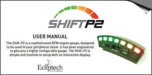
The Shift-P2 is a sophisticated RPM engine gauge, designed to be used in your peripheral vision.
It has been engineered to give you a highly configurable gauge.
The Shift-P2 is simple and intuitive to setup with an interactive display.
Preview Video
Shift-P2/P2+ Features Comparison
Warning System
When a warning is triggered (battery voltage, stall alert, channel 1, 2 or 3), the lights and display immediately show the warning and continue while the condition persists. The warning will stop if the condition for the warning is no longer met. For an analog channel input, this occurs when the voltage transitions past the off level.
If a button is pressed while a warning is being displayed, it is cancelled and will not automatically re-occur. A multi-function channel can be configured as an alternative cancel warning interface, where a push button should be used. If more than one warning is in effect, they will display using the priority order channel 1, 2, 3, engine stall and battery voltage alert. Using left/right, the display will normally cycle through RPM <> Battery <> Off, however if any cancelled warnings still meet their warning criteria, these will be shown while cycling these screens.
If a multi-function channel is linked to warning input channel, it’s output will be active while the warning is displayed. It will be inactive if the warning is cancelled or when configuring associated parameters.
The Shift-P2+ provides 3 auxiliary channels.
Each channel can be used as an input or output.
Each channel can be used as a low side output (open collector, up to 200mA) or as an analog voltage input. An internal 2.2kohm pull-up resistor can also be enabled.
The channels can be configured for a range of functions. For example: Use of an external buzzer for warnings and/or when shift point is reached. Switch input to dynamically change between user profiles. Tacho output to drive other devices. Stall alert output. Analog warning threshold input. This could be used to display a warning from a compatible sensor or another device (such as an external knock sensor unit). Light threshold output. Switch on an RPM threshold. Output switched in relation to another channels input voltage.
Some output functions provide options to pulse the output once, or pulse periodically. Trigger thresholds have adjustable on and off levels to provide switching hysteresis as well as to enable the logic to be inverted. Warnings are provided with a lights display and warning message on the display. These warnings can be cancelled using the front buttons or by configuring a channel as an cancel push button input.
- Tacho Output
- Square wave Tach Output for other devices. Support 1 pulse/rev or 1 pulse per 2 revolutions.
- Engine Stall Output
- Output activates while engine stall condition has been detected and warning is actively displayed
- RPM Threshold Output
- The output can be set active when the RPM is above or below a set value, with configurable hysteresis.
- RPM Last Stage Output
- Output is active while the last light stage is shown.
- Linked Channel Output
- This is an output, which is triggered by another input channel going active. A channel configured as either a “General Voltage Input” or a “Warning Input” can be linked to.
- Light Threshold Output
- The built in light sensor can be used to control a channels output. Brightness on and off levels can be adjusted, providing hysteresis. The brightness level used is independent of the adjustment associated with the lights brightness.
- External Buzzer Output
- An external buzzer can be connected to a channel. The buzzer can be enabled for multiple conditions.
- When the last lights display stage is shown.
- Engine stall condition.
- Battery voltage alert.
- Channel 1, 2 or 3 when configured as a General Voltage Input, Warning Input or RPM Threshold Output.
- As with the multi-function output capability, the buzzer can be set to pulse once, repeated or constant on while any of the enabled conditions exist. A buzzer rated for operation at ignition voltage is required. Connect the buzzers positive wire to the multi-function channel wire. Connect the negative buzzer wire to ground. The buzzer is powered via the outputs high side switch with 2.2kohm series resistor.
- General Voltage Input
- Assigning a channel as a general voltage input allows it to be used in association with the Linked Channel Output, or to trigger the external buzzer output. The thresholds and logic state are set via the voltage on and off levels.
- Profile switch
- Enabling a channel as a profile switch provides an external means of dynamically changing between the two profiles. Changing between profiles occurs with seamless operation. For example, the second profile could be used for an alternative fuel saving RPM range. Or if you were using this on two vehicles, you could connect a channel input to +12V on one vehicle and ground on the other. Set this channel as the profile switch and the Shift-P2 will automatically change profile depending on which of the two vehicles you plug it in too.
- Warning Input
- An external analog signal can be connected and monitored by the Shift-P2. A turn on and turn off voltage level provides both range and hysteresis configuration. The lights warning display and label can be selected from provided options, which is specific for the channel used. A range of labels are provided, as well as the ability to select a single letter as the warning label. The function of the warnings is as previously described.
- Cancel Warning Input
- This feature enables an external push button to be used to cancel warnings. The operation of this is the same as described for using the buttons on the Shift-P2 to cancel warnings. It is recommend to connect the other end of the push button to ground and use the internal pullup enable.
- Staging Switch Input
- Staging mode can be automatically enabled when the RPM goes below a set level, for a set time period. However it can also be manually triggered and held on by an external signal with this function. For example, a transbrake or handbrake switch could be used to hold the Shift-P2 in staging mode. Once released it will turn off according to the auto-off system, which gives more flexibility. For example, transition to driving display sequence instantly, when above a set RPM for a period of time or when the last stage is reached in staging mode (shift point).
- Off
- Channel not turned off.
The available features are subject to addition, removal or change. This may be related to firmware installed or with updates.
Wiring & Compatibility
The Shift-P2 is designed to be compatible with a wide range of ignition systems.
Modern vehicles with coil-on-plug (including those with CAN Bus).
Compatible with multi-spark ignition systems.
ECUs with a Tach Output. 5V & 12V square/pulse signals.
Coil packs switched on the negative, including wasted spark.
Works with many distributors (please ensure no excessive contact bounce with mechanical distributors).
The Shift-P2 is not directly compatible with magneto ignition, capacitor discharge, condenser type ignition systems typically used on 2-stroke engines. It is not compatible or appropriate to connect to cam shaft position sensors. Do not attempt to connect directly to these signals, as damage may result to the unit and/or vehicle. The Shift-P2 is however compatible with these if the ECU has a dedicated tach output or a tacho converter is used with these ignition types.
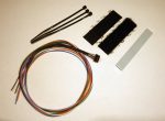
Requires only 3 wires to be connected, RPM (blue), Switched 12V (Red), Ground (Black).
A further 3 wires are provided for Shift-P2+ additional functionality (see User Manual).
Green = Channel-1 White = Channel-2 Orange = Channel-3
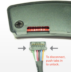
Connection
The cable supplied uses high quality lightweight flexible wires. The flat connector is intended for permanent installation purposes only. It is not intended as a connector that is regularly disconnected and reconnected. The connector will only fit with the correct orientation as shown. If you need to disconnect the Shift-P2, switch the power off and push the locking tabs shown to release. Recommended method is to use a small flat blade screwdriver to release one tab at a time.
Micro-USB socket is also included for future firmware updates that may be made available.
PDFs
Click to open in a new window.
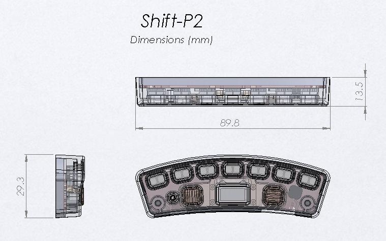
1:1 PDF Template
Print the PDF and make a paper cutout to check fitment on your vehicle.
PDF has dimensions.
Shift-P2 3D Model
Have a 3D printer and want to create your own mounting bracket?
Download the STL/STEP/IGS files of the Shift-P2 and bracket as a reference for your design.
Included in the download are two examples for a flat base.
These were designed to glue the Shift-P2 to the base. The second model has provision for removable adhesive tape in the base for mounting in vehicle.
These are files/images are references for supporting the 3D printing community. Ecliptech does not provide these parts.
If you have a drawn a bracket, share your design. We will post here for others!
Please note. Do not remove the rear cover or disassemble the unit. Doing so introduces the risk of electrostatic damage to the sensitive electronics and therefore voids the warranty.
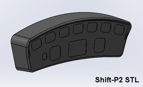
Example Bracket
A flat base conversion, suitable for 3D printing. Click image to download the STL.
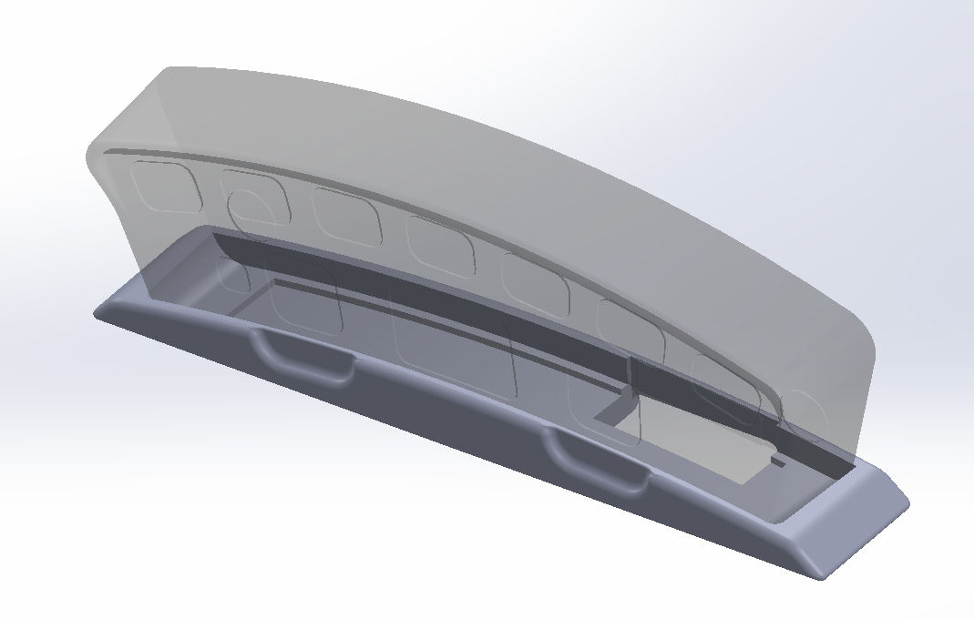
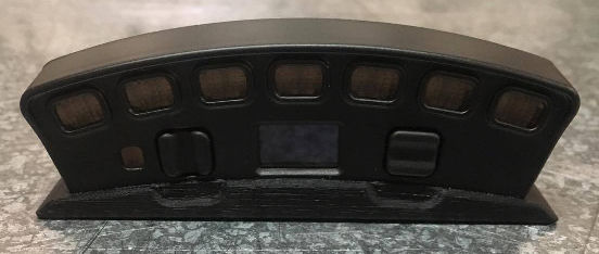
Thanks to Damien, Main North Automatics, for design input and printing.
Shift-P2 Firmware
All units currently shipping from Ecliptech have the latest V17 firmware. You can check the version System –> Product Info and then scroll down.
The only reason to update the firmware for earlier versions, is if you want to disable the auto-off timer for the display screen or use the lights sequence 19. It also has a tweak for P2+ users that can prevent external warnings triggering when ignition first turned on.
If you have an earlier model with the RPM pullup function, which you are using, do not update. This feature was removed as it was too convenient to “try it” without understanding the risks.
If you have a PC with Window 10, it’s pretty straight forward. Install the download tool, unzip and load the firmware file, connect to the Shift-P2 using a micro-USB and then download.
Early versions of Windows you will likely need to first install a very common FTDI USB driver. I cannot provide technical support for PC drivers issues. Refer to the FTDI website.
The firmware update won’t erase your configuration. The same firmware is used for both the P2 and P2+.
Specific Fitment Guides
Ecliptech maintains a database on wiring colours, which we expand at every opportunity. We are quite happy to provide any fitment advice we have to offer.
We really do appreciate all those people that have contacted us with more detailed information. Ecliptech have put a few specific fitment guides together, however many have been contributed by the public. Credit is always given to the author, so please feel free to send us your fitment notes. These guides are available to download below, however please use the information at your own risk.
CARS
We have wiring information for some cars… please contact us with year/model for advise.
Good wiring resources are: www.modifiedlife.com & www.the12volt.com
- BMW MC 1995
- Chevy Cavalier 2.2L EcoTec 2005
- Corvette C6 Z06 2006
- Ford Falcon AU
- Ford Falcon BA-BF
- Holden Commodore VY II SS
- Holden Commodore VE
- Honda Civic EP3 Type R 2001..2005
- Honda Integra Type R 1999
- Honda S2000 2006
- Lotus Elise/Exige S1
- Lotus Elise/Exige S2
- Mazda Miata
- Mitsubishi EVO X
- Nissan Silvia S15 2000
- Porsche 911 Carrera
- Porsche 964..993
- Porsche Boxster S, 2000
- PRB Birkin S3 Clubman
- Smart Fortwo 451 2008
- Subaru Forester GT 1999
- Subaru WRX 2000
- Subaru WRX 2001/2
- Toyota 86GT
- Toyota Corolla Sportivo 2005
- Volkswagen R32 MKIV
- Volkswagen Golf GTI MKVI
MOTORBIKES
We have wiring information for a lot of bikes… please contact us with year/model for advise.
- Benelli TNT Sport, 2006
- Buell Firebolt
- Buell Lightening
- BMW R1200GS
- Harley XL1200C Sportster 2005
- Honda VFR400
- Honda CBR600RR 2005
- Honda CBR600RR 2007
- Honda CBR250RR
- Honda CBR250R
- Honda CBR600F
- Honda Hornet 250
- Honda VTR250
- Kawasaki ZXR250
- Kawasaki ZX6R 1995
- Kawasaki ZX6R 2002
- Kawasaki ZX7R 1996-2003
- Kawasaki ZX10R 2007
- KTM950 2005..06
- KTM950 SM
- Suzuki GSF1250S
- Suzuki GSXR600 2001
- Suzuki GSXR750 2006
- Suzuki GSXR1000 2008s
- Suzuki SV1000
- Suzuki TLR1000
- Triumph Daytona 600 2004
- Triumph Daytona 675 2006
- Yamaha YZF-R1 2004
- Yamaha YZF-R6 1999..2002
How quick does the display register the RPM?
Very very quick! The RPM measurement algorithm does not use the basic pulse counting technique, or basic frequency to voltage converters. The RPM is digitally calculated per pulse! The digital filter algorithm is biased to displaying an increase of RPM quickly and accurately, while also filtering any electrical noise. The exact time is quite dependent on the frequency of the tacho signal. This level of precision and speed is what makes them an ideal visual reference for drag and motorsport racing. The Shift-P2 is likely more accurate and faster than most tacho gauges.
How bright are the lights?
Each light actually has TWO LEDs. They are quite bright and can be viewed from a wide angle! Even with full sun shining on them, you can still see them clearly. They were designed to be bright enough for use on motorbikes, with a wide viewing angle. The in-built light sensor however does a fantastic job of reducing the brightness when the ambient light drops off, which is adjustable.
Can I have them Flash at just the Shift Point?
Yes! One of the provided display modes will flash all the lights only when you exceed your set RPM point, just like a traditional shift light. Or you can program a specific display sequence with the Shift-P2+ model.
Can I Turn the display off?
Yes! Use left or right to cycle the display to “Off” temporarily. If you are driving your mother-in-law around and need to keep the engine roar down, you can set the lights to default to the “Off” mode at ignition on. If however your passenger won’t stop talking, press a button and the lights will again let you know where the shift point is. Warnings are still active when the lights are set to off.
How do I customising the lights display?
The Shift-P2+ model provides the feature to customise the lights display.
You have up to 15 Stages (16 including the first with all lights are off).
You don’t have to use all 15. You can use 5 if you want.
The RPM is equal between all the stages, however you can always (for example) make two consecutive stages identical. That will give a wider gap between lights changing.
The little arrow starts on the stage number. That is the stage you are adjusting. Up/Down to go to the next/previous stage.
Move the arrow to the right once. If you press Up, you toggle this stage between flashing and not flashing. Press down and you turn the stage off, making this stage and all higher ones not used. This is how to reduce the number of stages used.
Move the arrow to the right again and you are on the first light. Up/Down to change its colour (or turn off, no-colour).
Move the arrow to the other lights and change them too.
Take the arrow back to the left and change to the next stage… and customise this how you want.
Individual light colours available… red, green, blue, amber, yellow, cyan, olive, magenta, white, light green and pink.
How are they mounted?
Both a performance acrylic adhesive foam pad and adehesive backed Velcro (brand) for automotive use are included. These have excellent resistance to ageing, water, most solvents and UV light. They stick really well to plastic, but not to vinyl (particularly those with protective waxes applied). Alternative mounting plates may be available in the future.
Can I mounts the lights external?
This is not possible. They are an internal component in a sophisticated electronics assembly.
Is the Shift-P2 Waterproof?
It is not waterproof. The Shift-P2 must be mounted behind a windscreen, where it is not subjected to the wind pressure or rain. Ecliptech may make a waterproof variant in the future. Please contact us if interested.
Warranty
The Shift-P2 has a 24 month warranty from date of purchase, return to base. This covers manufactured defects, not damage. If you ever have a problem with one of our products, please contact us!